

A single incorrect reading on a Tier 1 worksite doesn't just lead to a minor technical error; it can compromise an entire facility's compliance under the latest AS/NZS 3000:2026 Wiring Rules. Learning how to use a multimeter with precision is the fundamental skill that separates a safe, efficient technician from one who risks damaging expensive infrastructure. We recognize the pressure to deliver accurate data while navigating the complexities of modern CAT ratings and the rigorous safety principles required by the AS/NZS 62368.1:2026 standard.
It's common to feel a sense of hesitation when faced with unfamiliar symbols or inconsistent readings that threaten your data integrity. This guide provides the technical roadmap you need to master essential measurements for voltage, resistance, and continuity while meeting strict Australian industrial benchmarks. We'll examine the specific safety requirements for AU worksites, decode equipment ratings, and outline the steps to ensure your readings are robust enough for NATA-endorsed compliance reporting. By the end of this manual, you'll have the confidence to diagnose electrical faults and maintain the high-performance standards your industry demands.
Key Takeaways
- Master the technical fundamentals of how to use a multimeter to diagnose complex electrical faults while maintaining strict adherence to the 2026 AS/NZS 3000 Wiring Rules.
- Correctly identify critical dial settings and symbols to distinguish between AC and DC voltage and accurately measure resistance for comprehensive circuit health assessments.
- Navigate the Measurement Category (CAT) system to ensure your equipment meets the mandatory safety requirements for specific Australian industrial environments.
- Implement the "Three-Point Test" method and proper probe orientation; these steps are essential for guaranteeing personal safety and data integrity during high-voltage testing.
- Understand the necessity of NATA-certified calibration to mitigate instrument drift; this ensures your readings remain compliant with international precision standards.
Understanding the Digital Multimeter (DMM): More Than Just a Screen
A digital multimeter (DMM) serves as the primary diagnostic interface between a technician and the complex electrical systems found in Australian industrial facilities. While basic models provide simple readings, professional grade units function as high-precision instruments capable of identifying subtle power quality issues before they lead to catastrophic equipment failure. Understanding what is a multimeter involves recognizing its role as a multi-functional integrator. The "multi" prefix signifies its capacity to measure voltage, resistance, and current within a single chassis, which is indispensable for troubleshooting the diverse circuitry governed by AS/NZS 3000:2026. We rely on these devices to provide the empirical data necessary for maintaining site safety and operational uptime.
In 2026, we prioritize True RMS (Root Mean Square) technology as a non-negotiable feature for industrial applications. Standard averaging meters often provide inaccurate data when measuring non-linear loads, such as variable speed drives or modern LED lighting systems common in Melbourne or Sydney manufacturing plants. True RMS ensures your readings account for the distorted waveforms these systems produce. This level of precision is vital when you are learning how to use a multimeter to verify that safety critical systems meet the strict 0.05% accuracy thresholds required for Tier 1 compliance.
Analogue vs. Digital: Why Precision Matters
The industry has shifted decisively away from analogue movements toward high-resolution digital displays. Digital LCDs eliminate the risk of parallax error, where a technician misreads a needle's position based on their viewing angle. This clarity is essential for high-stakes environments where a 1% deviation can lead to a regulatory breach. Because digital units offer superior stability and repeatable results, they are the mandatory standard for our electrical equipment calibration services. We find that digital processing allows for faster sampling rates, which helps capture transient spikes that analogue needles simply cannot track.
The Anatomy of a Professional Multimeter
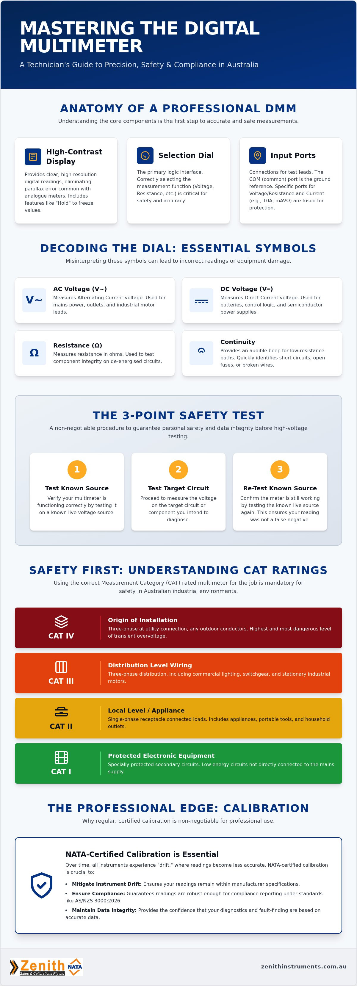
A professional DMM consists of three primary components: the high-contrast display, the selection dial, and the input ports. The selection dial acts as the logic gate for the internal circuitry, while the input ports require strict adherence to lead placement protocols. The COM (common) port remains the ground reference for all tests, while the 10A or mUA ports are specifically fused to protect the internal components during high-current measurements. The "Hold" function is a critical utility that freezes the displayed value, allowing you to maintain focus on probe placement in cramped or poorly lit industrial enclosures. Mastering these physical interfaces is the first step in understanding how to use a multimeter safely in a live environment.
Decoding Multimeter Symbols and Selection Dial Settings
Mastering the selection dial is a prerequisite for anyone learning how to use a multimeter in a professional capacity. The dial acts as the primary interface for the instrument's internal logic, directing the signal through specific shunt resistors or attenuators based on the chosen parameter. Misinterpreting these symbols doesn't just result in "ghost" readings; it can lead to catastrophic failure if an instrument is set to a low-impedance mode while connected to a high-energy source. We emphasize that every technician must verify their settings against the Essential Safety Criteria for electrical equipment before making contact with a live circuit.
The distinction between AC Voltage (indicated by V with a tilde ~) and DC Voltage (V with a solid and dashed line) is the most critical hurdle. AC settings are used for mains power and industrial motor leads, while DC is reserved for battery systems, control logic, and semiconductor power supplies. Resistance, represented by the Greek letter Omega (Ω), serves as the foundation for circuit health diagnostics. We use this setting to verify component integrity while the system is de-energised. Closely related is the continuity symbol, often depicted as a sound wave, which provides an audible alert for low-resistance paths. This is the fastest way to troubleshoot cable breaks or blown fuses in complex wiring looms.
Current measurement (A) requires the highest level of discipline. Unlike voltage testing, measuring current involves placing the meter in series with the load. If you leave your leads in the 10A port while attempting a voltage test, you effectively create a short circuit through the meter. Most professional units utilize high-energy ceramic fuses to mitigate this risk, but the resulting arc can still pose a significant safety hazard on industrial sites.
Standard Dial Symbols for Australian Technicians
Professional meters utilize a standardized set of icons to ensure cross-brand compatibility. Technicians should be fluent in the following:
- V and mV: Voltage and millivolts; essential for both power and sensitive signal testing.
- Ω: Resistance; used to identify "open" or "short" conditions in coils and resistors.
- Diode Arrow: Used for semiconductor diagnostics to verify the one-way flow of current.
- Capacitance (-| |-): Critical for HVAC technicians to test motor start and run capacitors.
Auto-Ranging vs. Manual Ranging
Auto-ranging simplifies the workflow for field technicians in Sydney or Brisbane by automatically selecting the most appropriate decimal precision for the detected signal. However, in environments with fluctuating signals, the meter may "hunt" for a range, causing a delay in data capture. We recommend switching to manual ranging when you need to lock in a specific resolution for high-speed troubleshooting or when performing repetitive tolerance checks. You can use the "Range" button to cycle through fixed decimal points, ensuring the display stays stable during critical measurements. To maintain the precision of these sensitive internal circuits, we suggest regular calibration of your electrical test equipment to ensure every dial position remains within its specified tolerance.
Step-by-Step: Measuring Voltage, Resistance, and Continuity
Executing measurements in high-energy industrial environments requires a disciplined sequence to eliminate human error and instrument failure. When we train technicians on how to use a multimeter, we mandate the "Three-Point Test" method for verified safety. This protocol involves testing your meter against a known live source, measuring the target circuit, and then re-verifying the meter against the known live source. This ensures that a blown internal fuse or a fractured lead hasn't provided a false negative reading, which is a critical step for maintaining compliance with Australian safety standards.
Correct probe orientation is the golden rule of electrical diagnostics. The black lead must always stay in the COM (Common) port, while the red lead is placed in the VΩ port for most tasks. Consistency here prevents polarity confusion and protects the meter's sensitive internal shunts. For those seeking deeper technical insights into advanced diagnostic workflows, we recommend reviewing our Multimeter Guide 2026, which details specific applications for Sydney and Melbourne industrial sectors.
Interpreting the display correctly is just as vital as lead placement. If you see "OL" on the screen, it stands for "Overload" or "Open Loop." In resistance mode, this signifies that the resistance is higher than the meter can measure, effectively indicating an open circuit. In voltage mode, it warns that the potential exceeds the current range. We never treat "OL" as a zero reading; doing so in a high-voltage environment can have lethal consequences.
Measuring Voltage (AC and DC)
- Step 1: Rotate the selection dial to the correct voltage type. Use V~ (AC) for mains power and industrial motor leads, or V- (DC) for battery systems and control logic.
- Step 2: Connect the probes in parallel across the component. Unlike current testing, you don't break the circuit; you simply "bridge" the two points of potential.
- Step 3: Observe the reading for stability. If the values fluctuate wildly, it may indicate "ghost voltage" caused by capacitive coupling from adjacent live wires.
Testing Continuity and Resistance
The most important rule for resistance testing is that the circuit must be completely de-energised. Attempting to measure ohms on a live circuit will likely damage the meter's input protection. We use the continuity "beep" function for rapid wire tracing in complex industrial looms; a clear tone confirms a continuous path, while silence indicates a break. When reading specific Ohm values, a result of "Zero" indicates a direct short or perfect continuity, whereas "Infinity" (OL) confirms a complete break in the circuit integrity.
Safety Standards and CAT Ratings for Australian Workplaces
Adherence to safety standards is not merely a recommendation; it is a legal requirement under the AS/NZS 3000:2026 Wiring Rules. When we discuss how to use a multimeter in an industrial capacity, we must prioritize the Measurement Category (CAT) rating of the instrument. These ratings define the meter's ability to withstand transient voltage spikes, which are high-energy surges that can occur when heavy machinery switches or during atmospheric disturbances. A meter with an insufficient CAT rating can fail catastrophically, posing a direct threat of arc flash or explosion to the technician.
A common but dangerous error is using a CAT II rated meter on a main switchboard in a Melbourne manufacturing plant. CAT II instruments are designed for single-phase, receptacle-connected loads like office equipment. For main distribution boards and three-phase circuits, a CAT III or CAT IV rating is mandatory. We emphasize that your choice of hardware must match the energy levels present at the point of measurement. Beyond the meter itself, you must ensure your leads are fused and the probe insulation remains intact. High-quality probes often feature wear-indicator insulation, showing a different color when the outer layer is compromised.
We mandate a rigorous visual inspection of every digital multimeter (DMM) before it touches a live circuit. This checklist includes:
- Confirming the CAT rating is appropriate for the specific test point.
- Inspecting leads for cracks, frays, or exposed copper.
- Verifying the probe tips are secure and free from oxidation.
- Checking the casing for impact damage or signs of internal overheating.
Understanding CAT III and CAT IV Ratings
CAT III ratings cover the three-phase distribution level, including commercial lighting systems and fixed motor installations. CAT IV is the most stringent category, required for measurements at the utility connection, service entrance, or any outdoor conductors. Industrial power grids frequently experience significant transient voltage risks due to inductive load switching. Using a CAT IV 600V meter provides a higher level of protection against these transients than a CAT III 600V unit, even though the steady-state voltage limit appears identical.
Common Beginner Mistakes to Avoid
The most frequent error we encounter is attempting to measure voltage while the leads are still plugged into the 10A current port. This creates a direct short circuit through the meter's internal shunt. While professional meters use high-energy ceramic fuses to mitigate this, the resulting arc can still be hazardous. Always check your internal fuses after any high-current measurement to ensure the meter remains functional. Finally, never operate a meter with a cracked screen or damaged housing, as these defects compromise the instrument's dielectric strength. To ensure your safety equipment meets these rigorous benchmarks, we provide NATA-certified electrical calibration services to verify both accuracy and protection circuits.
The Professional Edge: Why Multimeter Calibration is Non-Negotiable
Mastering the technical steps of how to use a multimeter is only half of the equation; the reliability of the resulting data depends entirely on the instrument's current calibration status. Every digital multimeter is subject to "instrument drift." This phenomenon occurs as internal voltage references and precision resistors age or succumb to the thermal stresses of Australian industrial environments. Even high-tier instruments can provide readings that fall outside of the strict 0.05% accuracy thresholds required for safety-critical systems if they aren't regularly serviced. We've seen how minor deviations in resistance readings can lead to false passes during continuity testing, which compromises site safety.
We provide a comprehensive multimeter calibration service that addresses these deviations, ensuring your equipment remains a dependable source of truth. As the premier partner for instrument calibrations in Australia, we align our technical processes with the latest ISO standards. This commitment protects your facility from the legal and operational risks associated with inaccurate data and regulatory non-compliance under the 2026 frameworks.
NATA vs. Traceable Calibration
Many technicians confuse standard traceable calibration with NATA-endorsed certification. While a traceable check confirms a meter is within specification, a NATA-certified certificate is the primary trust signal required for high-stakes projects. Medical and aerospace sectors in Sydney require this level of precision to meet rigorous safety audits. It provides an unbroken chain of comparison to national standards, which is often a mandatory requirement for Tier 1 contractor sites. We recommend checking your calibration sticker monthly. If the interval has exceeded 12 months, your data integrity for compliance reporting is effectively compromised.
Zenith’s On-Site and Lab Calibration Solutions
We recognize that sending equipment to a laboratory can create logistical bottlenecks for large workshops. To solve this, we offer mobile service capabilities across Brisbane, Newcastle, Sydney, and Melbourne. This proactive model allows us to calibrate your entire inventory, from electrical testers to pressure gauge calibration, without removing critical tools from your production line. Our technicians provide rapid response times to minimize unplanned downtime. This ensures your site remains compliant with the AS/NZS 3000:2026 framework. Contact Zenith for a professional calibration quote today to secure your instrument's accuracy and your team's safety.
Securing Precision in Your Electrical Workflows
Mastering how to use a multimeter is a career-long commitment to precision that directly impacts the safety and efficiency of Australian industrial sites. We've explored the critical importance of selecting the correct CAT ratings to mitigate transient voltage risks and the necessity of using True RMS technology for modern, non-linear loads. By adhering to the Three-Point Test method and maintaining a disciplined approach to dial settings, you ensure that every reading serves as a reliable data point for compliance reporting. This technical expertise is the foundation of professional electrical diagnostics.
Precision is only sustainable when supported by rigorous maintenance. Zenith Sales & Calibrations stands as your dependable expert, offering NATA Accredited Laboratories and an Australia-wide mobile service to keep your instruments within tolerance. Our ISO 9001 compliant quality management systems guarantee that your equipment meets the highest international standards. Ensure your equipment meets NATA standards; book a Multimeter Calibration with Zenith today. We look forward to partnering with you to maintain the exactness your specialized industry requires.
Frequently Asked Questions
How do I know if my multimeter is accurate?
The only definitive way to verify accuracy is by checking for a current calibration sticker and a valid NATA-endorsed certificate. While you can perform a field check against a known voltage source, this doesn't account for instrument drift across all ranges. Professional technicians rely on annual laboratory certification to ensure their readings meet the strict 0.05% accuracy thresholds required for industrial compliance and safety reporting.
What is the difference between AC and DC on a multimeter?
AC (Alternating Current) settings measure voltage that periodically reverses direction, which is the standard for Australian mains power and industrial motors. DC (Direct Current) measures a constant, one-way flow of electricity found in batteries, solar arrays, and control logic circuits. Understanding this distinction is a fundamental part of learning how to use a multimeter, as selecting the wrong mode will result in zero or highly inaccurate readings.
Can I use a multimeter to test a car battery?
Yes, you can test a car battery by setting your dial to DC voltage (V-). A fully charged lead-acid battery should show approximately 12.6 volts when the engine is off. If the reading drops below 12.2 volts, the battery is likely discharged or failing. This same technique applies to verifying backup power supplies in telecommunications and data center environments across Sydney and Melbourne.
What does "True RMS" mean on a digital multimeter?
True RMS (Root Mean Square) describes an instrument's ability to accurately measure non-linear AC waveforms. Standard averaging meters provide incorrect data when testing modern equipment like variable speed drives or LED lighting systems that produce distorted waves. For industrial technicians, a True RMS meter is essential because it provides the "heating value" of the current, ensuring safety and precision in complex power environments.
How often should a professional multimeter be calibrated in Australia?
Industry standards in 2026 mandate that professional multimeters undergo calibration every 12 months. This interval is necessary to maintain the integrity of your data for ISO 9001 quality systems and to ensure compliance with AS/NZS 3000 safety requirements. Frequent use in harsh regional environments can accelerate instrument drift, making regular servicing at an accredited laboratory a non-negotiable requirement for technical excellence.
Is it safe to measure a wall socket with any multimeter?
No, it is only safe if the meter carries a minimum safety rating of CAT III 300V or higher. Using a basic hobbyist meter or one with a CAT II rating on a high-energy mains socket can lead to catastrophic failure if a transient voltage spike occurs. Always inspect your leads for insulation damage and confirm the instrument's category rating before attempting to measure any live mains-connected infrastructure.
What happens if I use the wrong setting on my multimeter?
Selecting the wrong setting often results in a blown internal fuse or, in extreme cases, damage to the meter's internal circuitry. The most dangerous error involves attempting to measure voltage while the leads are in the 10A current port, which creates a direct short circuit. While professional-grade meters feature high-energy ceramic fuses to mitigate these risks, the resulting arc can still pose a safety hazard to the operator.
How do I test a fuse using a multimeter?
To test a fuse, set your dial to the continuity or resistance (Ω) mode. Touch the probes to both ends of the fuse; a continuous beep or a reading near zero ohms confirms the fuse is functional. If the display shows "OL" (Open Loop), the internal element has melted and the fuse must be replaced. This is a primary diagnostic step when troubleshooting how to use a multimeter for industrial fault finding.